Tracking Africa Systems

The simple fuel flow meter is designed for the measurement of fuel consumption in the fuel lines of vehicles and stationary machines, as well as for monitoring the operating time in different engine operating modes. The simple fuel flow meter is used to measure the consumption of the following fluids: Gas oil heating oil other liquid fuels and mineral oils with a kinematic viscosity of 1.5 to 6 mm2 / s. The Simple Fuel Flow Meter is a direct fuel consumption measurement tool, used as part of the GPS tracking system, vehicle telematics system or as a standalone (standalone) solution for fuel consumption monitoring.

Tasks

Fuel theft prevention

Fuel consumption monitoring

Engine diagnostics

Machine runtime monitoring

Digital meters and built-in battery

All data is recorded in digital meters in the internal memory of the simple fuel flow meter. This ensures data security and protection against manipulation and interference by third parties. In addition, the meters record data even if the external power is turned off. After switching on again, all data is sent to the telematics unit.

Fraud protection

The simple fuel flow meter has two special counters, which record attempts by third parties to influence the operation of the flow meter – « tampering » and « interference » counters. The « Interference » meter protects the simple fuel flow meter from the impact of magnetic fields aimed at stopping the measurement of fuel consumption.

The “tampering” meter records attempts by third parties to tamper with flowmeter data by generating artificial fuel consumption (eg by blowing air through the measuring chamber). In either case, the simple fuel flow meter will start recording the duration of the influence and send an alarm to a telematics unit.

Consumption and operating time counters

Fuel consumption

• instantaneous fuel consumption, L / H
• Hourly fuel consumption in the “Forward” line
• Hourly fuel consumption in the “Return” line
• Total fuel
consumption , L • Total fuel consumption in the “idle” mode of operation of the engine
• Total fuel consumption in « optimal » mode of engine operation
• Total fuel consumption in « overload » mode of engine operation
• Total fuel consumption in « negative » mode of flowmeter operation (feedback exceeds supply)

Engine running time

• total operating time, h
• Total operating time in “Idling” motor operating mode
• Total operating time in “optimal” motor
operating mode • Total operating time in “Overload” motor operating mode
• Total operating time in « negative » operating mode of the flowmeter
• Total operating time of the supply chamber
• Total operating time of the return chamber
• Operating time of the supply and return chambers in each mode engine operation

Special

• Engine operating time in “tampering” mode, h
• Engine operating time in “Interference” mode, h
• Current engine operating mode according to fuel consumption rate
• fuel temperature
• Correction status of the temperature
• Correction coefficient value
• Battery charge

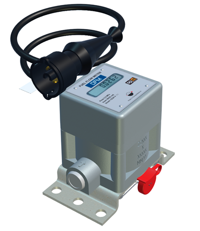
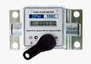
Fuel flow meter with LCD display. Autonomous and economical solution for measuring fuel consumption.

Fuel flow meter with output cable (interface) to send the signal to the tracking unit. Efficient solution for online monitoring of fuel consumption in the telematics system.

Output signal cable + integrated LCD display. Combination of a stand-alone fuel meter and an online solution for fuel monitoring in a telematics system.

DFM display information

The simple fuel flow meter with display enables stand-alone measurement of fuel consumption without data transfer to a server. This solution is mainly used for small fixed units or for small fleets operating in a closed area.

DFM display screens:

Total fuel
consumption Total fuel consumption meter with higher numbering capacity
Engine run
time Engine run time in standby mode Engine run
time in optimum mode
Engine run time in overload mode


Fuel consumption in sabotage mode
Interference time
Instantaneous fuel consumption
Battery charge in percentage at maximum
Temperature in measuring chamber Firmware version

Is it possible to trick the simple fuel flow meter?

The single fuel flow meter is installed directly in the vehicle’s fuel line (between the engine end of the fuel tank) and enables rapid detection of fuel theft. The simple fuel flow meter is reliably protected against cheating and vandalism. The operation of the simple fuel flow meter cannot be influenced without leaving a trace.

• The solid metal body of the single fuel flow meter provides reliable protection against dust and dirt, as well as attempts to deactivate the flow meter.
• Protection against the influence of a strong magnetic field. In the event of electromagnetic interference, the flowmeter records the duration of action on the special « Interference » timer.
• Tampering with the air flow is unnecessary! If the fuel consumption rate is higher than usual, the simple fuel flow meter  records the sabotage time on a special « tampering » counter.
• Long battery life. The single fuel flow meterscan work from the built-in battery for three years. When disconnected from the on-board power supply network, the simple fuel flowmeter  still records the data and stores it in its own memory.
• Sealing of the flowmeter and fuel circuit elements. It is impossible to intervene on the site where the flowmeter is installed without damaging the gaskets.

Simple fuel flow meter installation and connection

Simple fuel flow meters are installed directly in the engine fuel line:

• before the low pressure pump – on the “suction side”, or
• after the low pressure pump – on the “pressure side”.

The exact installation mode is chosen based on the specifications of the fuel system. Installation diagrams are described in the documentation of the simple fuel flow meter .

Templates

Single fuel
flow meter 50 Single fuel flow
meter 100 Single fuel flow meter 250 Single fuel
flow meter 500

Nominal bore

6
6
8
12

Starting flow rate, l / h

0.5
0.5
2
5

MIN flow rate, l / h

1
2
5
10

MAX flow, l / h

50
100
250
500

Recalibration interval, l

000 100
100 000
250 000
500 000

Characteristics

Connection thread ………………………………………………………… M14x1.5

Nominal pressure, MPa ………………………………………………………… .0,2

MAX pressure, MPa ……………………………………………………………… ..2,5

Supply voltage, V ……………………………………………………… .10-50

Surge protection, V ………………………………………… ≤100

Current consumption, mA (24 V / 12 V), mA …………………… ..25 / 50

Operating temperature (without / with display), ° C ……… -40 .. + 80 / -20 .. + 60

Protection index ……………………………………………………………… .IP54

Relative precision error per chamber,%, not more than …………… 1